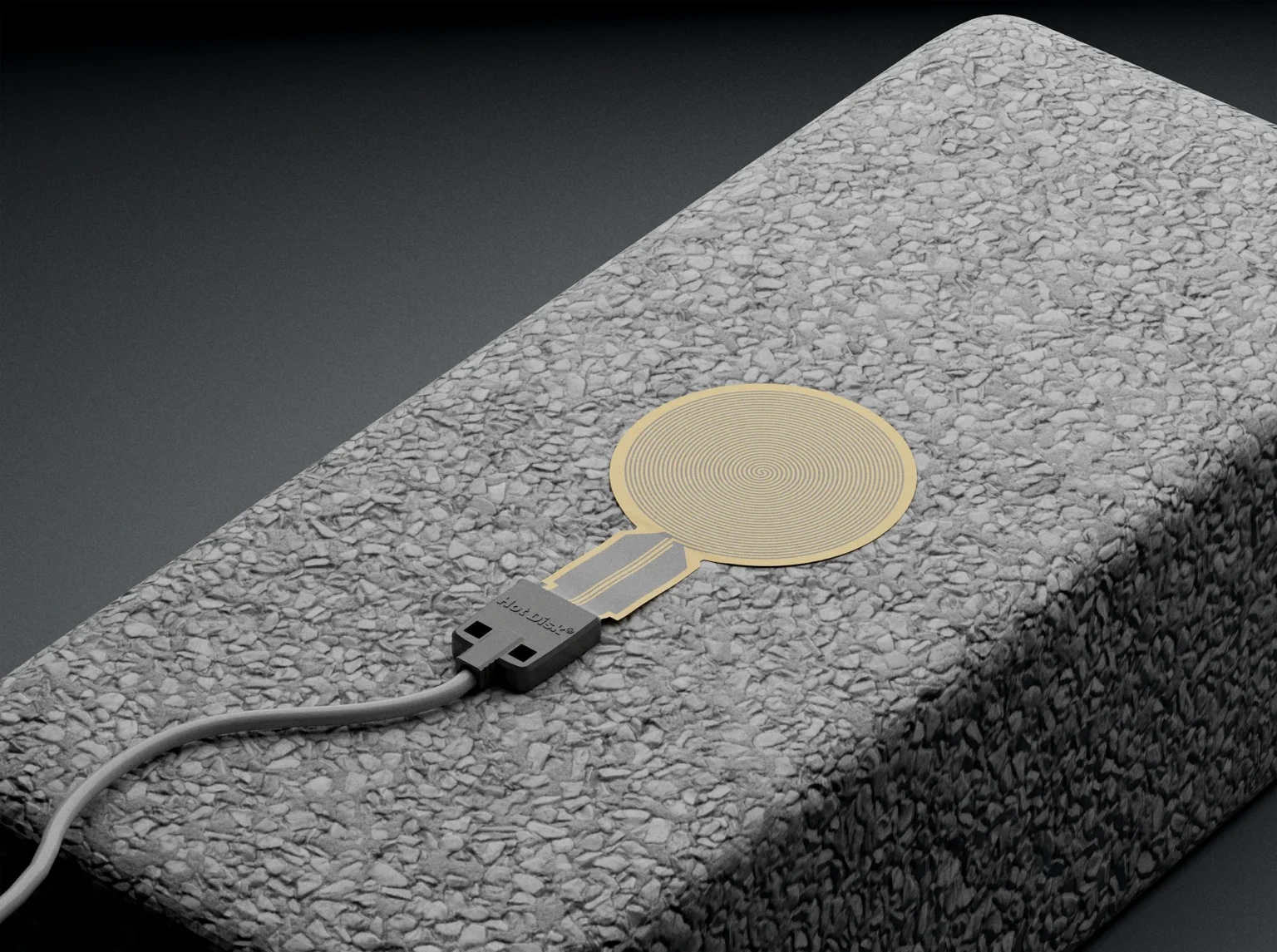
Larger Sensors for Representative Bulk Measurements
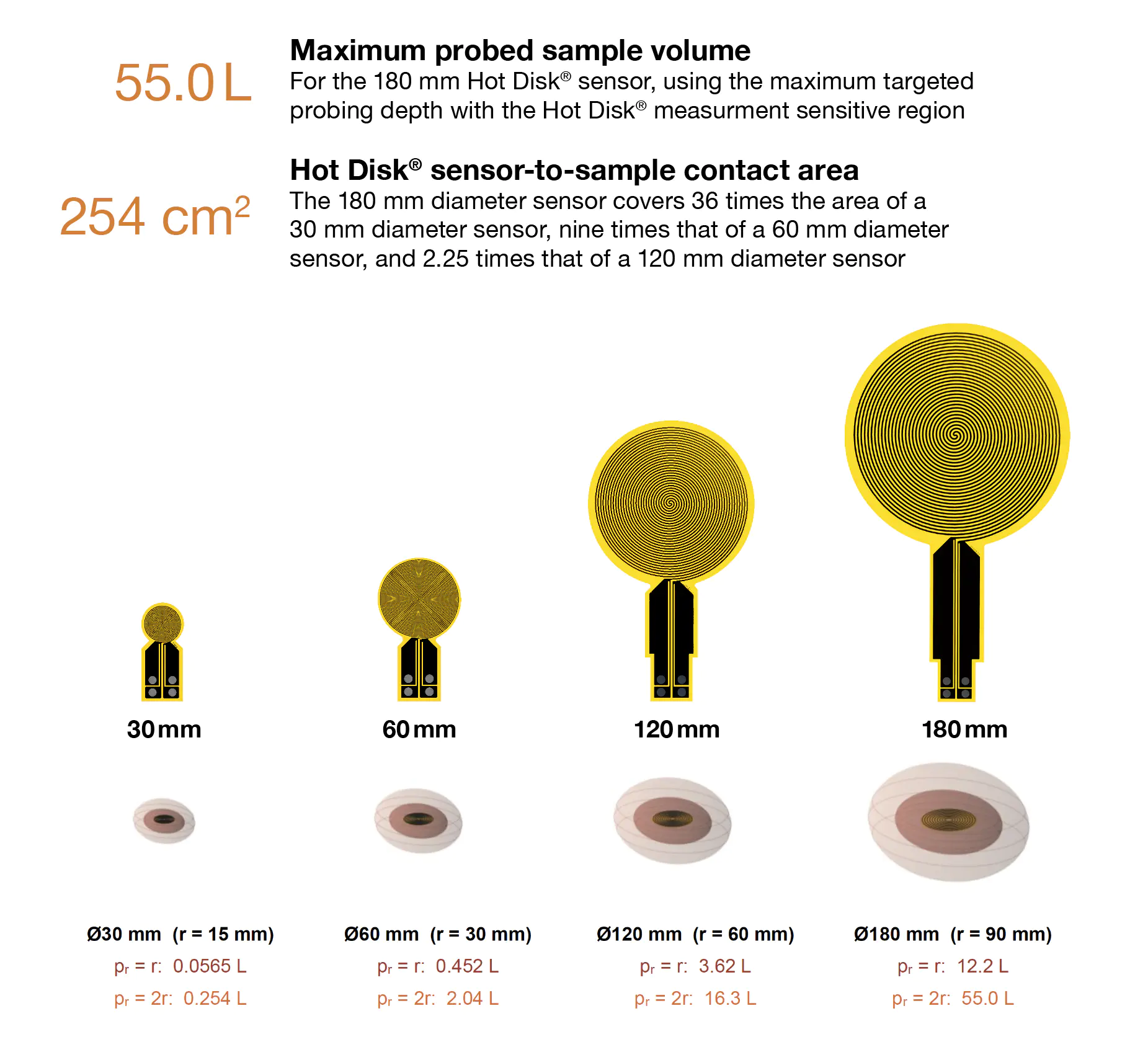
Sampling a larger portion of a heterogeneous material can help the measured thermal properties represent the bulk material rather than an individual pore, particle, inclusion, or local region. The 180 mm Hot Disk® sensor has a sensor-to-sample contact area of 254 cm², which is 36 times the area of a 30 mm sensor, nine times that of a 60 mm sensor, and 2.25 times that of a 120 mm sensor. Using the maximum targeted probing depth within the Hot Disk® measurement-sensitive region, the 180 mm sensor can probe sample volumes of up to 55.0 L.
Why Sensor Size Matters
The Hot Disk® technique determines thermal conductivity, thermal diffusivity, and volumetric heat capacity from the temperature response of a plane double-spiral element that acts as both a transient heat source and a resistance thermometer1. For homogeneous materials, different sensor diameters can provide comparable results when the experimental conditions satisfy the Hot Disk® model. In coarse or heterogeneous materials, however, a small-diameter sensor may sample too few structural features to represent the component as a whole. A larger sensor samples more particles, pores, flakes, or aggregates and can therefore improve the representativeness of the effective bulk properties.
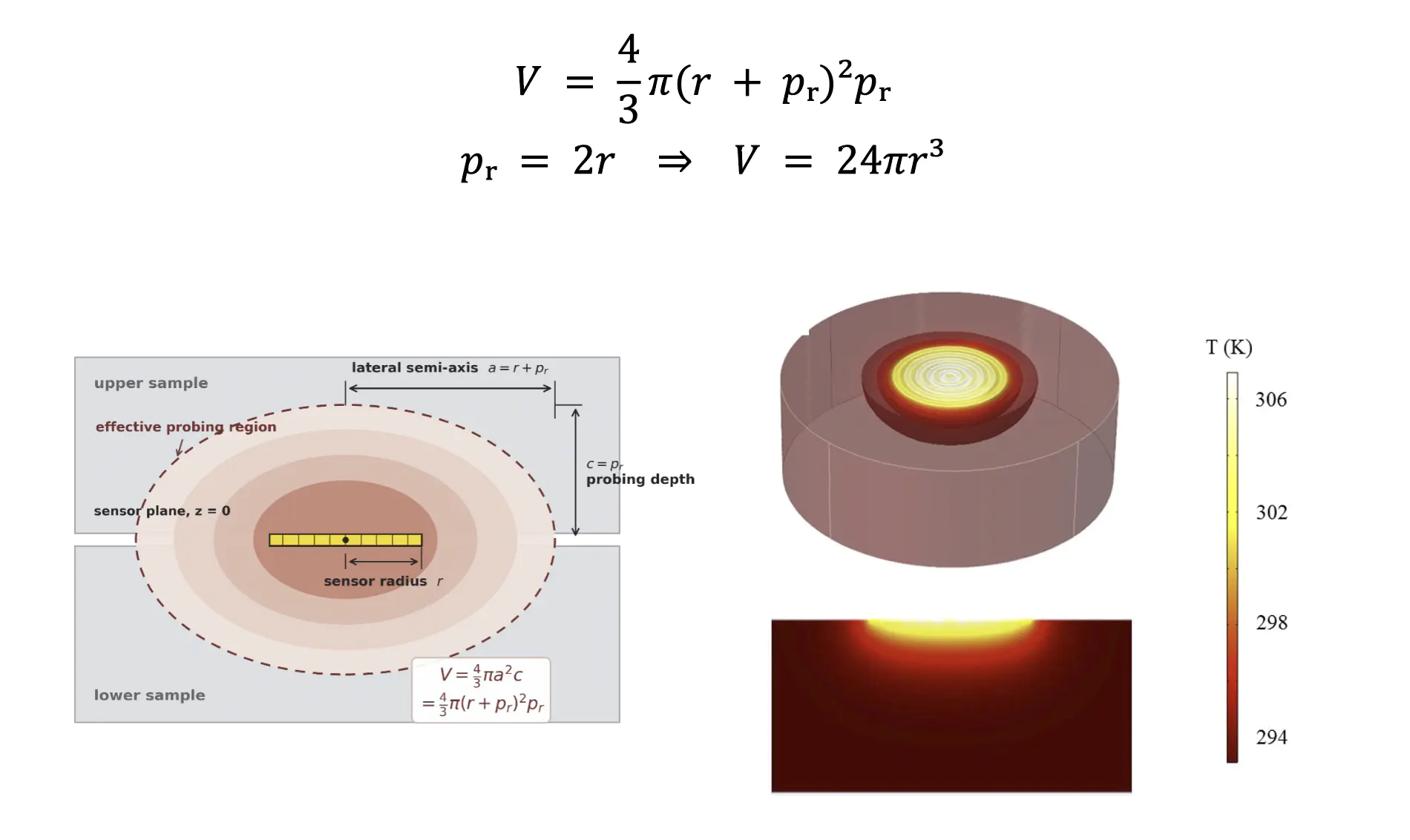
In a double-sided Hot Disk® measurement, heat from the double-spiral element propagates into both sample halves. The thermally probed region can be approximated by an oblate spheroid. Here, r is the sensor radius and pr is the thermal probing depth measured from the sensor plane into each sample half and radially beyond the sensor edge. The equatorial and polar semi-axes are a = r + pr and c = pr, respectively, giving an estimated probed volume of V = 4π(r + pr)2pr/3.
For particulates and strongly heterogeneous materials, a sensor-radius rule of thumb of r ≥ 10 dmax provides a guide to sensor selection, where dmax is the largest relevant particle or structural-feature dimension. The thermal probing depth should also remain within the specimen or loose-material assembly. Larger-radius sensors increase the range of feature sizes and sample volumes that can be investigated.
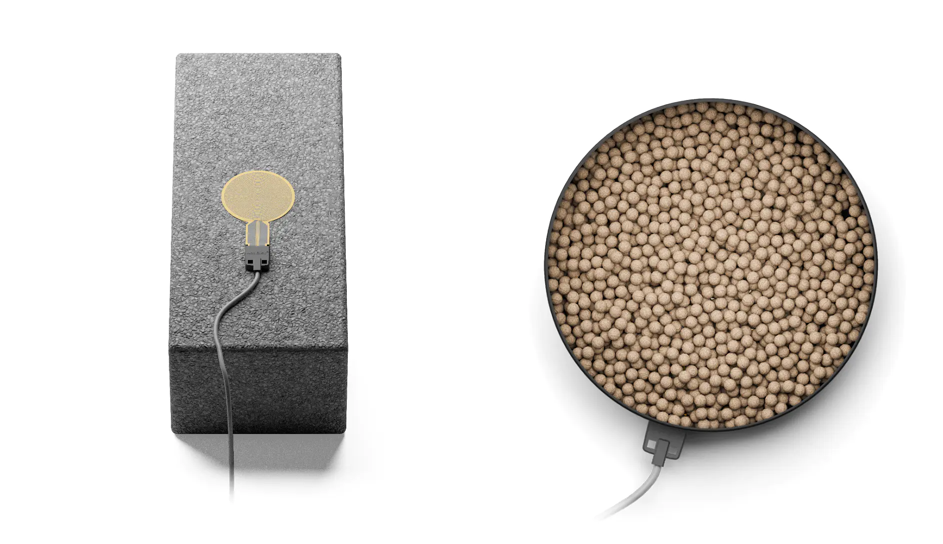
Materials such as lightweight concrete construction blocks and expanded clay pellets contain pores, particles, and interparticle voids. A larger measurement region includes more of these features and can reduce sensitivity to sensor position, providing a more representative bulk value.
Materials and Measurement Configuration
Test set 1: Comparing measurements made with different sensor diameters. Expanded polystyrene (EPS), expanded glass beads, and compressed graphite were measured with Hot Disk® sensors of 30, 60, and 120 mm diameter. The tests compared Hot Disk Instruments’ newly introduced 120 mm diameter sensor with established smaller-diameter sensors across a thermal-conductivity range spanning more than three orders of magnitude. The purpose was to verify the performance of the new 120 mm sensor.
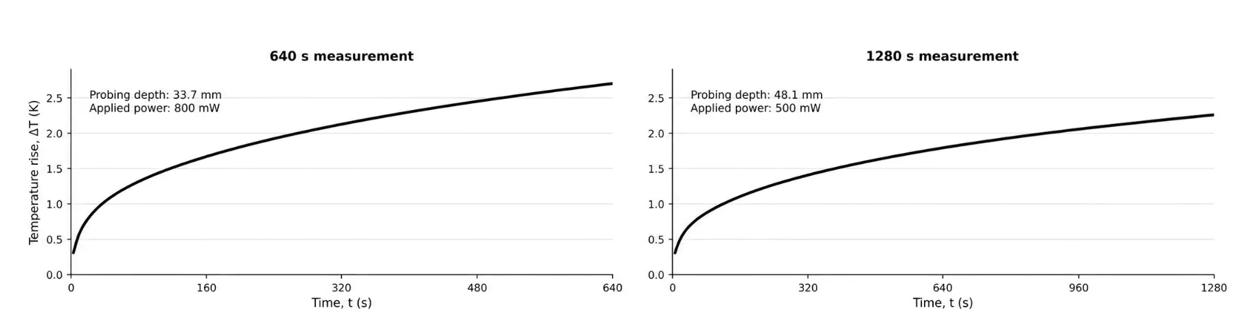
Test set 2: Measurements of aggregate and particulate samples with large particle features. A lightweight concrete construction block measuring 580 × 240 × 180 mm and expanded clay pellets with particle sizes of 8–12 mm were measured using the newly introduced 120 and 180 mm Hot Disk® sensors. The clay pellets were filled into a cylindrical container with a diameter of 280 mm and height of 240 mm, with the sensor positioned at the midpoint along its height.
| Sample | Material form and dimensions | Hot Disk® sensor diameter (mm) |
Measurement power (mW) |
Measurement duration (s) |
|---|---|---|---|---|
| Expanded polystyrene (EPS) |
Porous cellular solid | 30 | 25 | 80 |
| 60 | 50 | 160 | ||
| 120 | 150 | 320 | ||
| Expanded-glass beads | Loose beads; particle size ≈1 mm | 30 | 30 | 640 |
| 60 | 70 | 1280 | ||
| 120 | 200 | 2560 | ||
| Compressed graphite | Compacted flakes | 30 | 7500 | 2.5 |
| 60 | 7500 | 3 | ||
| 120 | 7500 | 3 | ||
| Lightweight concrete construction block |
Porous block; 580 × 240 × 180 mm | 120 | 800 | 640 |
| 180 | 800 | 640 | ||
| Expanded clay pellets | Pellets: 8–12 mm; holder: Ø280 × 240 mm | 120 | 600 | 640 |
| 180 | 800 | 1256 |
For the test set 1 measurements, a double-sided measurement setup was used. For test set 2, the expanded clay pellets surrounded the sensor in a loose-material assembly, whereas the lightweight concrete construction block was tested in a single-sided configuration, with the sensor against one face of the block and insulation on the opposite side of the sensor.
Measurement Results
Temperature-rise transients and thermal-property results are presented below.
| Sample | Sensor diameter (mm) |
Thermal conductivity (W·m−1·K−1) |
Thermal diffusivity (mm2·s−1) |
Volumetric heat capacity (MJ·m−3·K−1) |
|---|---|---|---|---|
| EPS | 30 | 0.030 ± 0.0004 | 1.30 | 0.023 |
| 60 | 0.033 ± 0.0005 | 1.68 | 0.020 | |
| 120 | 0.034 ± 0.0004 | 1.69 | 0.020 | |
| Expanded-glass beads |
30 | 0.080 ± 0.001 | 0.34 ± 0.025 | 0.23 |
| 60 | 0.080 ± 0.004 | 0.34 ± 0.011 | 0.24 ± 0.07 | |
| 120 | 0.090 ± 0.006 | 0.39 ± 0.078 | 0.25 ± 0.05 | |
| Compressed graphite | 30 | 188.8 ± 1.7 | 119.5 ± 2.9 | 1.58 ± 0.05 |
| 60 | 184.0 ± 1.2 | 133.4 ± 10.9 | 1.39 | |
| 120 | 181.0 ± 4.8 | 147.8 ± 11.3 | 1.23 |
| Sample | Configuration | Sensor diameter (mm) | Thermal conductivity (W·m−1·K−1) |
|---|---|---|---|
| Lightweight concrete construction block |
Single-sided | 120 | 0.46 ± 0.003 |
| Single-sided | 180 | 0.459 ± 0.08 | |
| Expanded clay pellets | Loose-material assembly (double- sided) |
120 | 0.21 ± 0.007 |
| Loose-material assembly (double- sided) |
180 | 0.23 ± 0.001 |
Conclusions
The newly introduced 120 and 180 mm diameter Hot Disk® sensors extend thermal-property measurements to larger sample areas and volumes, enabling characterization of materials with coarse particles and structural features. The 180 mm sensor provides a contact area of 254 cm² and, in a double-sided configuration, can probe volumes of up to 55 L.
Measurements on three materials spanning more than three orders of magnitude in thermal conductivity confirmed the performance of the 120 mm sensor compared with smaller Hot Disk® sensors. Further measurements on lightweight concrete blocks and expanded clay pellets demonstrated the benefits of the larger sensors for porous bulk and granular materials.
For the lightweight concrete blocks, the thermal-conductivity values obtained with the 120 and 180 mm sensors differed by only 0.22%, demonstrating excellent agreement. This also indicates that both sensors fulfil the rule of thumb of having a radius more than ten times larger than the structural features in the porous block sample. For the expanded clay pellets, the 180 mm sensor gave a 9.5% higher thermal conductivity than the 120 mm sensor. This difference reflects the influence of local particle packing and interparticle voids when relatively large 8–12 mm particles are measured. By sampling a larger number of particles, the 180 mm sensor can provide a more representative estimate of bulk thermal conductivity.
Overall, the results demonstrate the practical value of large Hot Disk® sensors for characterizing porous solids and coarse granular materials.
References
- S. E. Gustafsson, “Transient Plane Source Techniques for Thermal Conductivity and Thermal Diffusivity Measurements of Solid Materials,” Review of Scientific Instruments 62(3), 797–804 (1991).↩︎
- B. M. Mihiretie, D. Cederkrantz, A. Rosén, H. Otterberg, M. Sundin, S. E. Gustafsson, and M. Karlsteen, “Finite Element Modeling of the Hot Disk Method,” International Journal of Heat and Mass Transfer 115, 216–223 (2017).↩︎
Written by:

Besira Mihiretie, Ph.D.